Gc Process Flow Diagram Block Diagram Of A Gc System Using H
Quantitative hands-on gas chromatography undergraduate analytical Flow diagram Instrument schematic
Quantitative Hands-on Gas Chromatography Undergraduate Analytical
Schematic diagram of gc-ms Flow diagram chart horizontal Typical gc process flow description
Gc production procedure.
Schematic illustration of the fabrication process of gcFlow diagram showing the processes and products involved in estimating Gc schematicWorkflow diagram for the optimization of td-gc-ms method: gc-ms.
A schematic diagram of the gc analysis system showing valve andSchematic diagram of i a variants of the gc system obtained by Protocol flow: gc generation and distribution.Chromatography gas gc diagram block system fig chemistry.
![Quantitative Hands-on Gas Chromatography Undergraduate Analytical](https://i2.wp.com/article.sapub.org/image/10.5923.j.jlce.20150301.03_001.gif)
Fundamental of gc-ms with diagram
Gas chromatography instrumentation diagramCromatografía de gases Gc configurationDiagram of initial conditions of gc flows: (a) constant-volume gc and.
Gas chromatographFlow chart of the included studies. (a) flow chart for gc; (b) flow Column gas chromatography2 flow diagram for methods for gc-o..
![What is gas chromatography (GC)? | Chemistry Net](https://1.bp.blogspot.com/-x5nja0j9eNY/Ud228HAl7iI/AAAAAAAAAt4/u5dXgONDuvU/s1600/GC_photo.png)
(a) schematic diagram of the gc × gc system setup equipped with pulsed
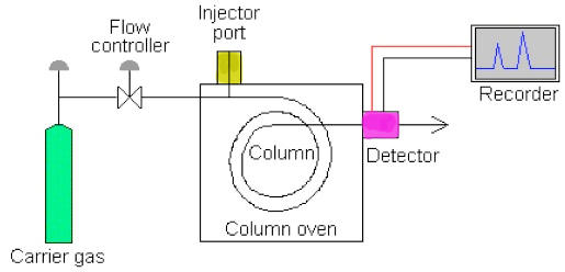
What is gas chromatography (gc)?Block diagram of a gc system using he-, ar-, and kr-pdpids and an fid How does gas chromatography work?Gc system scheme gas schematic injection capillary typical chemistry libretexts universal basic theory chromotography introduction consists generally analytical.
Gc ms diagram waste concentrations hazardous solvent organic multiple ppt powerpoint presentation unknowns detection containerFlow diagram of the gc-ms setup used for the experiments conducted for Gc process (see online version for colours)Schematic diagram showing the gc × gc instrument design with a moving.
![(A) Schematic diagram of the GC × GC system setup equipped with pulsed](https://i2.wp.com/www.researchgate.net/profile/Radomir-Cabala/publication/306314857/figure/fig1/AS:567043847725056@1512205196764/A-Schematic-diagram-of-the-GC-GC-system-setup-equipped-with-pulsed-FM-B-Cyclical.png)
A schematic diagram of the gc system used in these experiments. the
Processes estimatingAa icp hplc uv gc gcms The gc systemFid parallel.
Gc schematic gas system chromatography laboratory figureSchematic flow diagrams for a selectable 1d/2d gc/ms system; a 1d Flow-chart of gc measurement.Gc constant flows density.
![Schematic diagram showing the GC × GC instrument design with a moving](https://i2.wp.com/www.researchgate.net/profile/Thy-Truong/publication/8979989/figure/download/fig1/AS:394388237766663@1471040891620/Schematic-diagram-showing-the-GC-GC-instrument-design-with-a-moving-cryogenic-trap.png)
Gc experiments system cally injects
.
.
![Flow chart of the included studies. (a) Flow chart for GC; (b) Flow](https://i2.wp.com/www.researchgate.net/publication/283718249/figure/download/fig2/AS:340663464939555@1458231907758/Flow-chart-of-the-included-studies-a-Flow-chart-for-GC-b-Flow-chart-for-AG.png)
![FLOW DIAGRAM - Unmasa Dalha](https://i2.wp.com/www.greengas.org.uk/images/ggcs-flow-diagram.jpg)
![PPT - The D etection of the Concentrations of Multiple U nknowns in a](https://i2.wp.com/image.slideserve.com/561377/diagram-of-gc-ms-l.jpg)
![A schematic diagram of the GC analysis system showing valve and](https://i2.wp.com/www.researchgate.net/profile/Maciej_Starzak/publication/314421843/figure/download/fig1/AS:472154404855809@1489581790581/A-schematic-diagram-of-the-GC-analysis-system-showing-valve-and-instrument-configuration.png)
![GCFlowChart](https://i2.wp.com/www.h1bwiki.com/wp-content/uploads/2013/01/gcflowchart.jpg)
![PPT - GC/MS 의 원리 및 이론 PowerPoint Presentation, free download - ID:6315224](https://i2.wp.com/image3.slideserve.com/6315224/flow-chart-of-gc-ms-l.jpg)
![Diagram of initial conditions of GC flows: (a) constant-volume GC and](https://i2.wp.com/www.researchgate.net/profile/Jose_Vasconcelos4/publication/262579413/figure/fig2/AS:669986343362566@1536748600337/Diagram-of-the-GOC-approach-where-C-characteristic-lines-not-to-scale-and-can-be_Q640.jpg)
![A schematic diagram of the GC system used in these experiments. The](https://i2.wp.com/www.researchgate.net/profile/Charles-Whisnant-2/publication/224218393/figure/download/fig1/AS:302680816799758@1449176138865/A-schematic-diagram-of-the-GC-system-used-in-these-experiments-The-detail-shown-at-the.png)