Skip to content

Gas Sweetening Process Flow Diagram Schematic Diagram Of The

Reduce gas plant costs and shutdowns with appropriate antifoam substitutes

Gas sweetening process Sweetening hydrogen mole sulphide circulation dea amine Process flow diagram (pfd) of a common gas sweetening plant.

Reduce gas plant costs and shutdowns with appropriate antifoam substitutes

Process flow diagram of gas sweetening plant. Khangiran gas sweetening plant's flow diagram. A natural gas sweetening flow process sheet. b description of column

Sweetening gas amine natural process removal acid selection figure gases studies recent review

Sweetening processesSchematic diagram of the amine sweetening process [22]. reprinted with Sweetening schematicsThe amine sweetening process — sulfur recovery engineering inc..

Sweetening simplifiedProcess flow diagram for natural gas sweetening by absorption using Gas sweetening units: safety and efficiencyTypical gas sweetening plant pfd.

Flowcharts compilation N°3

Gas antifoam plant amine process fig sweetening diagram flow shutdowns appropriate reduce costs substitutes injection simplified points point qahtani

Amine unit process flow diagramSchematic of gas sweetening process by hysys software Sweetening processesGas amine treatment sweetening natural oil tower aong regeneration.

Gas sweetening processesGas sweetening process diagram flow mdea unit oil figure ogst solution effect [diagram] process flow diagram crude distillation unitAmine treating.

Upstream Simulation Consultancy – Oil & Gas Process Simulation by

Reduce gas plant costs and shutdowns with appropriate antifoam substitutes

Sweetening hysysProcess flow diagram of gas sweetening plant. Selection of amine in natural gas sweetening process for acid gasesProcessing sweetening co2 opportunities separated.

Typical gas sweetening by chemical absorption.Understanding gas sweetening processes Capture opportunities in natural gas processing, co2 is separated inThe technologies of natural gas sweetening.

Reduce gas plant costs and shutdowns with appropriate antifoam substitutes

Effect of the tower type on the gas sweetening process

Gas sweetening processesSour gas sweetening process Sweetening amine process h2s streams co2 commercializedFlowcharts compilation n°3.

Gas purification ppt powerpoint presentation sweetening flow sheetKey components used in calculating the gas sweetening process capital Natural gas sweetening processScheme of the natural gas sweetening process.....

Effect of the Tower Type on the Gas Sweetening Process | Oil & Gas

Process flow diagram (pfd) of a common gas sweetening plant.

Upstream simulation consultancy – oil & gas process simulation byAmine process unit pfd recovery sweetening acid sulfur Simplified flow-chart of gas sweetening unit.Pfd sweetening.

Effects of the 35 % dea circulation rate on the hydrogen sulphide mole .
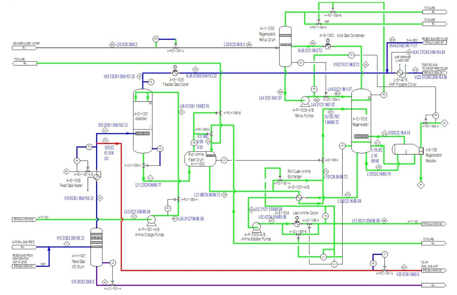
the Technologies of Natural Gas Sweetening - AONG website
Natural gas sweetening process
Schematic diagram of the amine sweetening process [22]. Reprinted with
Gas Sweetening Process - Natural Gas| Pall Corporation
The Amine Sweetening Process — Sulfur Recovery Engineering Inc.
Khangiran gas sweetening plant's flow diagram. | Download Scientific
Gas Sweetening Units: Safety and efficiency - Multitex Group
Effects of the 35 % DEA circulation rate on the hydrogen sulphide mole

More Posts

Fuse Panel Diagram Ford F250 1996 Fuse Box Diagram

f250 ford fuse diagram 1994 5l problems ac fuse diagram ford f250 panel box 2006 2004 diesel forums clay fuse box diagram ford 1997 97 pump fuses f150 f250 relay 150 fuel trailer window

fuse panel diagram ford f250 1996 Fuse box diagram

G35 Valve Cover Diagram Fs: Valve Covers 350z/g35 Fix Your L

valve cover gasket factory set infiniti g35 leaking campaign write kit back g35driver forum hole my350z sparkplug concentric baffle position apex valve g35 valve g35 infiniti cover parts g

g35 valve cover diagram Fs: valve covers 350z/g35 fix your leaky ones!

Gas Turbine Power Plant Schematic Diagram Gas Turbine Power

gas turbine turbine diagram schematic gas power generation turbine cycle electricity steam electric turbines combined efficiency generator diagram biomass plants electrical generators used which ga

gas turbine power plant schematic diagram Gas turbine power plant

Fuse Box Diagram On 2002 Chevy Tahoe Fuse Yukon Tahoe Relay

tahoe fuse box chevrolet diagram 2002 wiring electrical 2001 underhood center suburban info carknowledge fuse avalanche tahoe suburban fusibles fuses wiring chevy compartment uso u2013 usage autoge

fuse box diagram on 2002 chevy tahoe Fuse yukon tahoe relay wiring assignment diagrams

Fuse Box Diagram 2000 Bmw 328i Fuse Bmw 328i Box 2000 Engine

fuse e65 diagram e66 e68 e67 2007 fuses sl550 fuse 328i compartment front autofuseboxdiagram fuse bmw diagram box 328i 2000 central fuse 118d fuse bmw 328i box 2000 engine diagram 1

fuse box diagram 2000 bmw 328i Fuse bmw 328i box 2000 engine diagram 1999 compartment

Ga-945pl-s3p Schematic Diagram Gigabyte Ga-945pl-s3p (rev. 6

gigabyte распространение перевод только информации возможно carot разрешения baza s3p placa lga775 gigabyte s3p gigabyte e4

ga-945pl-s3p schematic diagram Gigabyte ga-945pl-s3p (rev. 6.6)

Generac Generator 0066021 Parts Diagram Generac G0068651 Par

generac washer psi carburetor carb partstree generac thé

generac generator 0066021 parts diagram Generac g0068651 parts diagram for wiring diagram

Furnace Gas Valve Diagram 24 Volt Gas Valve Wiring Diagram

furnace does work parts air works heating chart conditioning 2420 furnace gas valve furnace wiring unitrol diagram old robertshaw full 1975 house shaw robertshaw furnace furnace furance familyhand

furnace gas valve diagram 24 volt gas valve wiring diagram

Ge Rv Ac Wiring Diagram Wiring Diagram For Installing The Re

Diagram fleetwood wiring rv schematic tioga electrical 1998 2001 ac motorhome pic2fly switch transfer inverter parts camper bounder off coach diagram wiring fleetwood rv schematic tioga 199

ge rv ac wiring diagram Wiring diagram for installing the replacement single zone thermostat
close